Siemens 3RT5044-1AG20 коммутационное устройство
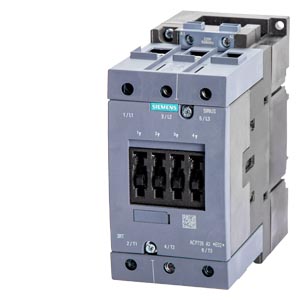
КОНТАКТОР 3-ПОЛ., AC-3, 30 КВТ/ 400 V, AC 110V 50/60ГЦ, ТИПОРАЗМЕР S3, ВИНТОВЫЕ КЛЕММЫ
Цена: по запросу
КОНТАКТОР 3-ПОЛ., AC-3, 30 КВТ/ 400 V, AC 110V 50/60ГЦ, ТИПОРАЗМЕР S3, ВИНТОВЫЕ КЛЕММЫ
Цена: по запросу
|
|
Contactor AC 110 V 50/60 HZ AC3 30 kW 400 V 3-pole, size S3 screw terminal | |||||||||||||||||||||||||
| product brand name | SIRIUS | |||||||||||||||||||||||||
| product designation | Power contactor | |||||||||||||||||||||||||
| product type designation | 3RT5 | |||||||||||||||||||||||||
| General technical data | ||||||||||||||||||||||||||
| size of contactor | S3 | |||||||||||||||||||||||||
| product extension auxiliary switch | Yes | |||||||||||||||||||||||||
| power loss [W] for rated value of the current | ||||||||||||||||||||||||||
| ● at AC in hot operating state per pole | 4.6 W | |||||||||||||||||||||||||
| ● without load current share typical | 6.75 W | |||||||||||||||||||||||||
| type of calculation of power loss current-dependent | quadratic | |||||||||||||||||||||||||
| insulation voltage rated value | 1 000 V | |||||||||||||||||||||||||
| degree of pollution | 3 | |||||||||||||||||||||||||
| surge voltage resistance rated value | 6 kV | |||||||||||||||||||||||||
| maximum permissible voltage for protective separation between coil and main contacts according to EN 60947-1 | 690 V | |||||||||||||||||||||||||
| shock resistance at rectangular impulse | ||||||||||||||||||||||||||
| ● at AC | 6.8 g / 5 ms, 4 g / 10 ms | |||||||||||||||||||||||||
| shock resistance with sine pulse | ||||||||||||||||||||||||||
| ● at AC | 10.6 g / 5 ms, 6.2 g / 10 ms | |||||||||||||||||||||||||
| mechanical service life (operating cycles) | ||||||||||||||||||||||||||
| ● of contactor typical | 10 000 000 | |||||||||||||||||||||||||
| ● of the contactor with added auxiliary switch block typical | 10 000 000 | |||||||||||||||||||||||||
| Substance Prohibitance (Date) | 03/01/2017 | |||||||||||||||||||||||||
| Net Weight | 1.71 kg | |||||||||||||||||||||||||
| Ambient conditions | ||||||||||||||||||||||||||
| installation altitude at height above sea level maximum | 2 000 m | |||||||||||||||||||||||||
| ambient temperature | ||||||||||||||||||||||||||
| ● during operation | -25 ... +60 °C | |||||||||||||||||||||||||
| ● during storage | -55 ... +80 °C | |||||||||||||||||||||||||
| Main circuit | ||||||||||||||||||||||||||
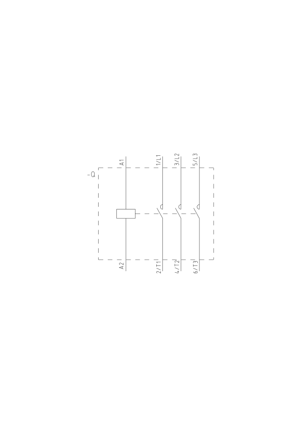
| number of poles for main current circuit | 3 | |||||||||||||||||||||||||
| number of NO contacts for main contacts | 3 | |||||||||||||||||||||||||
| number of NC contacts for main contacts | 0 | |||||||||||||||||||||||||
| operating voltage | ||||||||||||||||||||||||||
| ● at AC-3 rated value maximum | 1 000 V | |||||||||||||||||||||||||
| ● at AC-3e rated value maximum | 1 000 V | |||||||||||||||||||||||||
| operational current | ||||||||||||||||||||||||||
| ● at AC-1 up to 690 V | ||||||||||||||||||||||||||
| — at ambient temperature 40 °C rated value | 100 A | |||||||||||||||||||||||||
| — at ambient temperature 60 °C rated value | 90 A | |||||||||||||||||||||||||
| ● at AC-3 | ||||||||||||||||||||||||||
| — at 400 V rated value | 65 A | |||||||||||||||||||||||||
| — at 690 V rated value | 47 A | |||||||||||||||||||||||||
| ● at AC-3e | ||||||||||||||||||||||||||
| — at 400 V rated value | 65 A | |||||||||||||||||||||||||
| — at 690 V rated value | 47 A | |||||||||||||||||||||||||
| — at 1000 V rated value | 25 A | |||||||||||||||||||||||||
| connectable conductor cross-section in main circuit at AC-1 | ||||||||||||||||||||||||||
| ● at 60 °C minimum permissible | 35 mm² | |||||||||||||||||||||||||
| ● at 40 °C minimum permissible | 35 mm² | |||||||||||||||||||||||||
| operational current for approx. 200000 operating cycles at AC-4 | ||||||||||||||||||||||||||
| ● at 400 V rated value | 28 A | |||||||||||||||||||||||||
| ● at 690 V rated value | 20 A | |||||||||||||||||||||||||
| operating power | ||||||||||||||||||||||||||
| ● at AC-1 | ||||||||||||||||||||||||||
| — at 230 V at 60 °C rated value | 34 kW | |||||||||||||||||||||||||
| — at 400 V at 60 °C rated value | 59 kW | |||||||||||||||||||||||||
| — at 690 V at 60 °C rated value | 102 kW | |||||||||||||||||||||||||
| ● at AC-3 | ||||||||||||||||||||||||||
| — at 230 V rated value | 18.5 kW | |||||||||||||||||||||||||
| — at 400 V rated value | 30 kW | |||||||||||||||||||||||||
| — at 500 V rated value | 37 kW | |||||||||||||||||||||||||
| — at 690 V rated value | 45 kW | |||||||||||||||||||||||||
| ● at AC-3e | ||||||||||||||||||||||||||
| — at 230 V rated value | 18.5 kW | |||||||||||||||||||||||||
| — at 400 V rated value | 30 kW | |||||||||||||||||||||||||
| — at 500 V rated value | 37 kW | |||||||||||||||||||||||||
| — at 690 V rated value | 45 kW | |||||||||||||||||||||||||
| — at 1000 V rated value | 30 kW | |||||||||||||||||||||||||
| operating power for approx. 200000 operating cycles at AC-4 | ||||||||||||||||||||||||||
| ● at 400 V rated value | 15.1 kW | |||||||||||||||||||||||||
| ● at 690 V rated value | 18.6 kW | |||||||||||||||||||||||||
| no-load switching frequency | ||||||||||||||||||||||||||
| ● at AC | 5 000 1/h | |||||||||||||||||||||||||
| operating frequency | ||||||||||||||||||||||||||
| ● at AC-1 maximum | 1 000 1/h | |||||||||||||||||||||||||
| ● at AC-3 maximum | 1 000 1/h | |||||||||||||||||||||||||
| ● at AC-3e maximum | 1 000 1/h | |||||||||||||||||||||||||
| ● at AC-4 maximum | 300 1/h | |||||||||||||||||||||||||
| Control circuit/ Control | ||||||||||||||||||||||||||
| type of voltage of the control supply voltage | AC | |||||||||||||||||||||||||
| control supply voltage at AC | ||||||||||||||||||||||||||
| ● at 50 Hz rated value | 110 V | |||||||||||||||||||||||||
| ● at 60 Hz rated value | 110 V | |||||||||||||||||||||||||
| operating range factor control supply voltage rated value of magnet coil at AC | ||||||||||||||||||||||||||
| ● at 50 Hz | 0.8 ... 1.1 | |||||||||||||||||||||||||
| ● at 60 Hz | 0.85 ... 1.1 | |||||||||||||||||||||||||
| apparent pick-up power of magnet coil at AC | ||||||||||||||||||||||||||
| ● at 50 Hz | 247 VA | |||||||||||||||||||||||||
| ● at 60 Hz | 247 VA | |||||||||||||||||||||||||
| inductive power factor with closing power of the coil | ||||||||||||||||||||||||||
| ● at 50 Hz | 0.62 | |||||||||||||||||||||||||
| ● at 60 Hz | 0.62 | |||||||||||||||||||||||||
| apparent holding power of magnet coil at AC | ||||||||||||||||||||||||||
| ● at 50 Hz | 25 VA | |||||||||||||||||||||||||
| ● at 60 Hz | 25 VA | |||||||||||||||||||||||||
| inductive power factor with the holding power of the coil | ||||||||||||||||||||||||||
| ● at 50 Hz | 0.27 | |||||||||||||||||||||||||
| ● at 60 Hz | 0.27 | |||||||||||||||||||||||||
| Auxiliary circuit | ||||||||||||||||||||||||||
| number of NC contacts for auxiliary contacts instantaneous contact | 0 | |||||||||||||||||||||||||
| number of NO contacts for auxiliary contacts instantaneous contact | 0 | |||||||||||||||||||||||||
| operational current at AC-12 maximum | 10 A | |||||||||||||||||||||||||
| operational current at AC-15 | ||||||||||||||||||||||||||
| ● at 230 V rated value | 6 A | |||||||||||||||||||||||||
| ● at 400 V rated value | 3 A | |||||||||||||||||||||||||
| operational current at DC-12 | ||||||||||||||||||||||||||
| ● at 110 V rated value | 3 A | |||||||||||||||||||||||||
| ● at 220 V rated value | 1 A | |||||||||||||||||||||||||
| operational current at DC-13 | ||||||||||||||||||||||||||
| ● at 24 V rated value | 6 A | |||||||||||||||||||||||||
| ● at 110 V rated value | 1 A | |||||||||||||||||||||||||
| ● at 220 V rated value | 0.3 A | |||||||||||||||||||||||||
| contact reliability of auxiliary contacts | 1 faulty switching per 100 million (17 V, 1 mA) | |||||||||||||||||||||||||
| UL/CSA ratings | ||||||||||||||||||||||||||
| yielded mechanical performance [hp] for 3-phase AC motor at 460/480 V rated value | 50 hp | |||||||||||||||||||||||||
| Short-circuit protection | ||||||||||||||||||||||||||
| design of the fuse link | ||||||||||||||||||||||||||
| ● for short-circuit protection of the main circuit | ||||||||||||||||||||||||||
| — with type of coordination 1 required | fuse gL/gG: 250 A | |||||||||||||||||||||||||
| — with type of coordination 2 required | fuse gL/gG: 125 A | |||||||||||||||||||||||||
| ● for short-circuit protection of the auxiliary switch required | fuse gL/gG: 10 A | |||||||||||||||||||||||||
| Installation/ mounting/ dimensions | ||||||||||||||||||||||||||
| mounting position | +/-180° rotation possible on vertical mounting surface; can be tilted forward and backward by +/- 22.5° on vertical mounting surface | |||||||||||||||||||||||||
| fastening method side-by-side mounting | Yes | |||||||||||||||||||||||||
| fastening method | screw and snap-on mounting onto 35 mm and 75 mm DIN rail | |||||||||||||||||||||||||
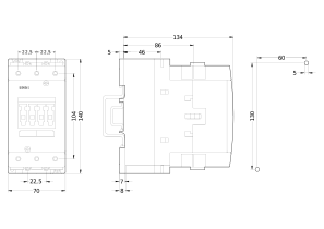
| height | 146 mm | |||||||||||||||||||||||||
| width | 70 mm | |||||||||||||||||||||||||
| depth | 139 mm | |||||||||||||||||||||||||
| Connections/ Terminals | ||||||||||||||||||||||||||
| type of electrical connection | ||||||||||||||||||||||||||
| ● for main current circuit | screw-type terminals | |||||||||||||||||||||||||
| ● for auxiliary and control circuit | screw-type terminals | |||||||||||||||||||||||||
| type of connectable conductor cross-sections for main contacts | ||||||||||||||||||||||||||
| ● solid or stranded | 2x (2.5 ... 16 mm²) | |||||||||||||||||||||||||
| ● finely stranded with core end processing | 2x (2.5 ... 35 mm²) | |||||||||||||||||||||||||
| ● finely stranded without core end processing | 2x (10 ... 35 mm²) | |||||||||||||||||||||||||
| type of connectable conductor cross-sections | ||||||||||||||||||||||||||
| ● for auxiliary contacts | ||||||||||||||||||||||||||
| — finely stranded with core end processing | 2x (0.5 ... 1.5 mm²), 2x (0.75 ... 2.5 mm²) | |||||||||||||||||||||||||
| ● for AWG cables for auxiliary contacts | 2x (20 ... 16), 2x (18 ... 14), 1x 12 | |||||||||||||||||||||||||
| Safety related data | ||||||||||||||||||||||||||
| product function mirror contact according to IEC 60947-4-1 | Yes | |||||||||||||||||||||||||
| Electrical Safety | ||||||||||||||||||||||||||
| protection class IP on the front according to IEC 60529 | IP20 | |||||||||||||||||||||||||
| touch protection on the front according to IEC 60529 | finger-safe, for vertical contact from the front | |||||||||||||||||||||||||
| Approvals Certificates | ||||||||||||||||||||||||||
|
||||||||||||||||||||||||||
| Further information | ||||||||||||||||||||||||||
|
||||||||||||||||||||||||||

|
||||||||||||||||||||||||||
|
||||||||||||||||||||||||||
| last modified: | 4/4/2026 | |||||||||||||||||||||||||
|
Date
4/8/2026 |
Subject to change without notice
© Copyright Siemens 2026 |
|||||||||||||||||||||||||



Все самое свежее о семинарах, обучениях, web-тренингах и новостях из мира АСУТП
Не допускается полное или частичное копирование материалов данного сайта без письменного разрешения владельца. Данный сайт использует технологию cookie. Оставаясь на сайте Вы подтверждаете свое согласие с использованием cookie. Правовая информация: Согласие пользователя на обработку персональных данных, Политика конфиденциальности и обработки персональных данных. На сайте указаны розничные цены без НДС. Для получения скидки обращайтесь в отдел продаж.
© ПРОМЭНЕРГО АВТОМАТИКА, 2001—2026. Все права защищены законодательством РФ.
Адрес офиса: Москва, ул. Скотопрогонная, д. 27/26, строение 1
{{ quickBuyNote }}


