|
|
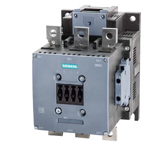
Contactor 110...127 V AC/DC AC3 132 kW 400 V AC (50...60 Hz) / DC operation auxiliary contacts 2 NO + 2 NC, 3-pole, size S10 bar connections conventional operating mechan. screw terminal
|
|
product brand name
|
SIRIUS
|
|
product designation
|
Power contactor
|
|
product type designation
|
3RT5
|
|
General technical data
|
|
size of contactor
|
S10
|
|
product extension auxiliary switch
|
Yes
|
|
power loss [W] for rated value of the current
|
|
|
● at AC in hot operating state per pole
|
18 W
|
|
● without load current share typical
|
7.4 W
|
|
type of calculation of power loss current-dependent
|
quadratic
|
|
insulation voltage rated value
|
1 000 V
|
|
degree of pollution
|
3
|
|
surge voltage resistance rated value
|
8 kV
|
|
maximum permissible voltage for protective separation between coil and main contacts according to EN 60947-1
|
690 V
|
|
shock resistance at rectangular impulse
|
|
|
● at AC
|
8,5 g / 5 ms, 4,2 g / 10 ms
|
|
● at DC
|
8,5 g / 5 ms, 4,2 g / 10 ms
|
|
shock resistance with sine pulse
|
|
|
● at AC
|
13,4 g / 5 ms, 6,5 g / 10 ms
|
|
● at DC
|
13,4 g / 5 ms, 6,5 g / 10 ms
|
|
mechanical service life (operating cycles)
|
|
|
● of contactor typical
|
10 000 000
|
|
● of the contactor with added auxiliary switch block typical
|
10 000 000
|
|
Substance Prohibitance (Date)
|
03/01/2017
|
|
SVHC substance name
|
Lead CAS-No. 7439-92-1
|
|
Net Weight
|
6.55 kg
|
|
Ambient conditions
|
|
installation altitude at height above sea level maximum
|
2 000 m
|
|
ambient temperature
|
|
|
● during operation
|
-25 ... +60 °C
|
|
● during storage
|
-55 ... +80 °C
|
|
Main circuit
|
|
number of poles for main current circuit
|
3
|
|
number of NO contacts for main contacts
|
3
|
|
number of NC contacts for main contacts
|
0
|
|
operating voltage
|
|
|
● at AC-3 rated value maximum
|
1 000 V
|
|
● at AC-3e rated value maximum
|
1 000 V
|
|
operational current
|
|
|
● at AC-1 up to 690 V
|
|
|
— at ambient temperature 40 °C rated value
|
330 A
|
|
— at ambient temperature 60 °C rated value
|
300 A
|
|
● at AC-3
|
|
|
— at 400 V rated value
|
265 A
|
|
— at 690 V rated value
|
265 A
|
|
● at AC-3e
|
|
|
— at 400 V rated value
|
265 A
|
|
— at 690 V rated value
|
265 A
|
|
— at 1000 V rated value
|
95 A
|
|
connectable conductor cross-section in main circuit at AC-1
|
|
|
● at 60 °C minimum permissible
|
185 mm²
|
|
● at 40 °C minimum permissible
|
185 mm²
|
|
operational current for approx. 200000 operating cycles at AC-4
|
|
|
● at 400 V rated value
|
117 A
|
|
● at 690 V rated value
|
105 A
|
|
operating power
|
|
|
● at AC-1
|
|
|
— at 230 V at 60 °C rated value
|
113 kW
|
|
— at 400 V at 60 °C rated value
|
197 kW
|
|
— at 690 V at 60 °C rated value
|
340 kW
|
|
● at AC-3
|
|
|
— at 230 V rated value
|
75 kW
|
|
— at 400 V rated value
|
132 kW
|
|
— at 500 V rated value
|
160 kW
|
|
— at 690 V rated value
|
250 kW
|
|
● at AC-3e
|
|
|
— at 230 V rated value
|
75 kW
|
|
— at 400 V rated value
|
132 kW
|
|
— at 500 V rated value
|
160 kW
|
|
— at 1000 V rated value
|
132 kW
|
|
operating power for approx. 200000 operating cycles at AC-4
|
|
|
● at 400 V rated value
|
66 kW
|
|
● at 690 V rated value
|
102 kW
|
|
no-load switching frequency
|
|
|
● at AC
|
2 000 1/h
|
|
● at DC
|
2 000 1/h
|
|
operating frequency
|
|
|
● at AC-1 maximum
|
800 1/h
|
|
● at AC-3 maximum
|
700 1/h
|
|
● at AC-3e maximum
|
700 1/h
|
|
● at AC-4 maximum
|
130 1/h
|
|
Control circuit/ Control
|
|
type of voltage of the control supply voltage
|
AC/DC
|
|
control supply voltage at AC
|
|
|
● at 50 Hz rated value
|
110 ... 127 V
|
|
● at 60 Hz rated value
|
110 ... 127 V
|
|
control supply voltage at DC rated value
|
110 ... 127 V
|
|
operating range factor control supply voltage rated value of magnet coil at DC
|
|
|
● initial value
|
0.8
|
|
● full-scale value
|
1.1
|
|
operating range factor control supply voltage rated value of magnet coil at AC
|
|
|
● at 50 Hz
|
0.8 ... 1.1
|
|
● at 60 Hz
|
0.8 ... 1.1
|
|
design of the surge suppressor
|
with varistor
|
|
apparent pick-up power of magnet coil at AC
|
|
|
● at 50 Hz
|
590 VA
|
|
● at 60 Hz
|
590 VA
|
|
inductive power factor with closing power of the coil
|
|
|
● at 50 Hz
|
0.9
|
|
● at 60 Hz
|
0.9
|
|
apparent holding power of magnet coil at AC
|
|
|
● at 50 Hz
|
6.7 VA
|
|
● at 60 Hz
|
6.7 VA
|
|
inductive power factor with the holding power of the coil
|
|
|
● at 50 Hz
|
0.9
|
|
● at 60 Hz
|
0.9
|
|
closing power of magnet coil at DC
|
650 W
|
|
holding power of magnet coil at DC
|
7.4 W
|
|
Auxiliary circuit
|
|
number of NC contacts for auxiliary contacts instantaneous contact
|
2
|
|
number of NO contacts for auxiliary contacts instantaneous contact
|
2
|
|
operational current at AC-12 maximum
|
10 A
|
|
operational current at AC-15
|
|
|
● at 230 V rated value
|
6 A
|
|
● at 400 V rated value
|
3 A
|
|
operational current at DC-12
|
|
|
● at 24 V rated value
|
6 A
|
|
● at 110 V rated value
|
3 A
|
|
● at 220 V rated value
|
1 A
|
|
operational current at DC-13
|
|
|
● at 24 V rated value
|
6 A
|
|
● at 110 V rated value
|
1 A
|
|
● at 220 V rated value
|
0.3 A
|
|
UL/CSA ratings
|
|
yielded mechanical performance [hp] for 3-phase AC motor at 460/480 V rated value
|
200 hp
|
|
Short-circuit protection
|
|
design of the fuse link
|
|
|
● for short-circuit protection of the main circuit
|
|
|
— with type of coordination 1 required
|
fuse gL/gG: 500 A
|
|
— with type of coordination 2 required
|
fuse gL/gG: 400 A
|
|
● for short-circuit protection of the auxiliary switch required
|
fuse gL/gG: 10 A
|
|
Installation/ mounting/ dimensions
|
|
mounting position
|
with vertical mounting surface +/-90° rotatable, with vertical mounting surface +/- 22.5° tiltable to the front and back
|
|
fastening method side-by-side mounting
|
Yes
|
|
fastening method
|
screw fixing
|
|
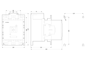
height
|
210 mm
|
|
width
|
145 mm
|
|
depth
|
202 mm
|
|
Connections/ Terminals
|
|
type of electrical connection
|
|
|
● for main current circuit
|
screw-type terminals
|
|
● for auxiliary and control circuit
|
screw-type terminals
|
|
type of connectable conductor cross-sections
|
|
|
● for auxiliary contacts
|
|
|
— finely stranded with core end processing
|
2x (0.5 ... 1.5 mm²), 2x (0.75 ... 2.5 mm²)
|
|
● for AWG cables for auxiliary contacts
|
2x (20 ... 16), 2x (18 ... 14), 1x 12
|
|
Safety related data
|
|
product function mirror contact according to IEC 60947-4-1
|
Yes
|
|
Electrical Safety
|
|
protection class IP on the front according to IEC 60529
|
IP00; IP20 with box terminal/cover
|
|
touch protection on the front according to IEC 60529
|
finger-safe, for vertical contact from the front with box terminal/cover
|
|
Approvals Certificates
|
|

|

|